Bent Bikerack
Designed for: Class - Product Design 3
Engineering Analysis for: Class - Mech 312 (FEA)


Engineering Simulations
I brought the bike rack that I designed in Product Design 3 into ANSYS and assigned it structural steel material properties. I then worked on applying the load. I initially applied a distributed load directly to the bike rack’s top surface but this resulted in an unrealistic deformation. To more evenly distribute the load a steel plate was added. The plate was connected to the bike rack using bonded contact. Unfortunately, the resulting deformation was still unrealistic.
The method that produced the most realistic deformation was using a block to act as the load. This block was fixed to the bike rack using bonded contact and a gravitational acceleration was applied to create the distributed load.

Simulation Setup
Most rod bike racks are designed to carry a load between 20 and 30 lbs, with some able to support over 80 lbs. To capture the full range of bike rack loading conditions, loads between 4 to 85 lbs were used in the simulations. The weight in ANSYS was changed by changing the material assignment of the block and thus its density. The angle of the load was also varied, between 45 and 90 degrees, this was done by changing the directional components of acceleration.
To fix the bike rack in place, fixed supports were applied at the seat tube connection holes and, depending on the simulation, either the top or bottom hub connection holes
Testing my Findings
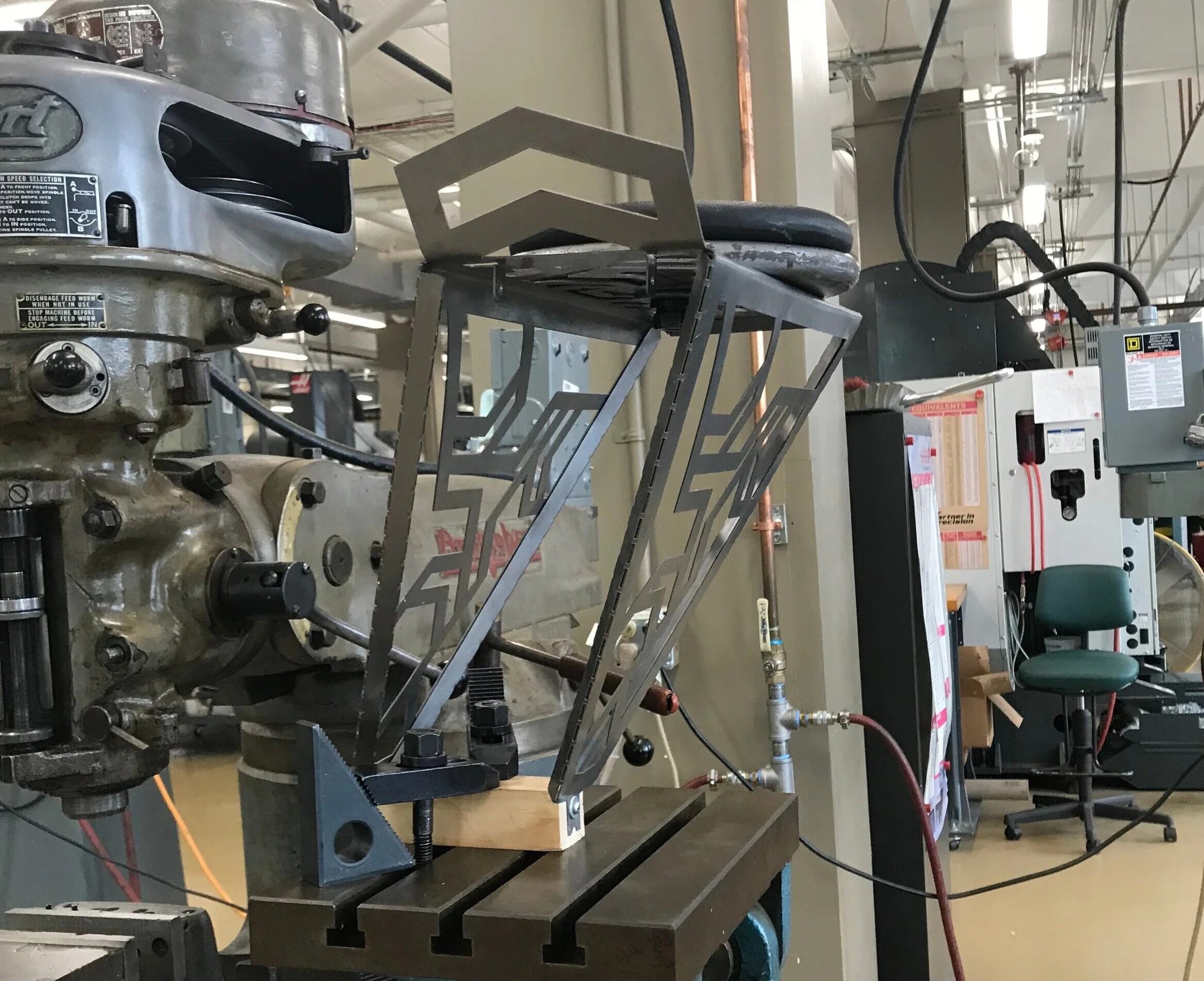
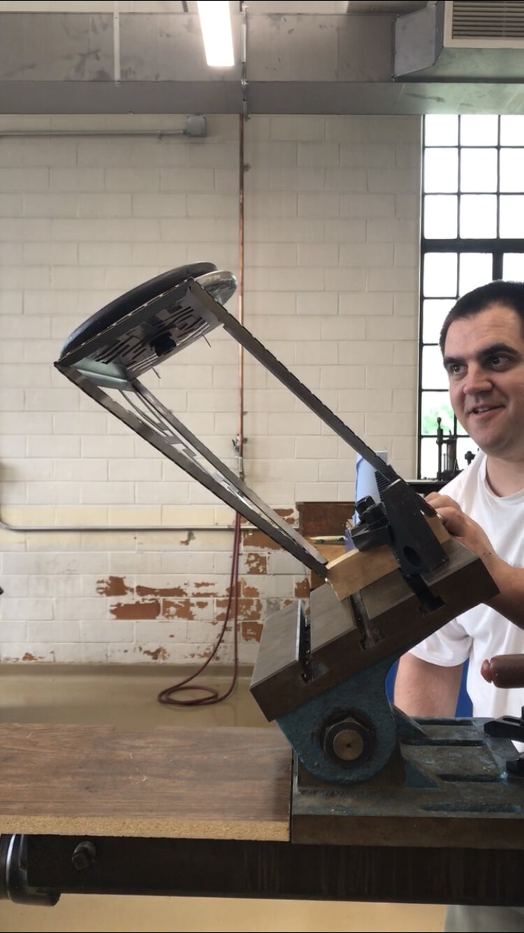
To test which angle would cause bike rack to buckle and determine where the buckling would occur in real life, I developed a sheet metal prototype and set it up the same way I did in ANSYS. I fixed the two sides where a bike wheel axis would be, applied a 20lbs load and adjusted the angle until the rack physically buckled.